Quick Start
This guide shows the fastest way to get your first output using the basic setup.
The process is organized into three practical levels: the initial setup (typically done only once), a session (your typical working period, usually one day), and the workflow cycle (the repeated sequence of steps performed for each sample).
Initial Setup
Prepare workspace → Install software → Assemble device
→ Connect device → Align lasers → Create new database
This step is performed once when installing and assembling the system.
Set Up Your Physical Workspace
Choose a stable desk or workbench with clear space below for the clamp mount. Ensure there is ~30 cm of free space on the surface to the left or right of your seat. For more details on space, environment, and operating conditions, see Workspace Requirements.
Install and Start the Software
Download and install the latest version of the LAP software. The installer creates two icons: Laser Aided Profiler and Deposit. Start the Laser Aided Profiler application and set aside the Deposit window.
Device Assembly
Start by unpacking the components one at a time as you assemble the device. Avoid touching the sensitive laser and camera components. Begin by securing the bottom part to your desk. Continue with the step-by-step instructions on the Device Assembly page.
Connect Device
Connect the main USB cable from the upper side of the USB hub to the USB 3.0 port of your computer. Ensure the device is detected. A green LED (indicator light) should be visible inside the top camera housing.
Align Lasers
To achieve optimal measurement accuracy, the two laser-projected lines must be precisely aligned, forming a so-called sheet of light. Proper alignment is critical for accurate results - refer to Laser Alignment for step-by-step instructions.
Create New Database
Create a new database to record your first sample. When starting out, you can use the minimal database setup - additional configuration can be done later.
Your First Session
Cameras → Calibrate system
At this point, the device should be connected and correctly detected by the software. A session represents your working period, typically one day.
Cameras
Remove all three camera protection lids.
Calibrate System
Calibration is essential for maintaining measurement accuracy and overall system precision. It should be performed once at the beginning of each session. See Calibration for detailed step-by-step instructions.
Workflow Cycle
Profile capture → Orient profile → Diameter capture
→ Camera snapshot → Save sample
At this point, the device should be connected, calibrated, and ready to capture your first sample. The workflow cycle is the sequence of steps repeated for each sample throughout your session.
ℹ️ Note: Each icon on the top bar represents an application mode. Clicking an icon toggles it on and off — while a mode is active, the drawing is temporarily replaced by the live view; click the same icon again to return to the drawing.
Profile Capture
The usual first step is capturing the main profile of a fragment. Open Laser Aided Profiler and switch to Capture Profile mode.
| Icon | Description | Toggle behavior |
|---|---|---|
 |
Capture Profile | Repeated clicks switch the mode on and off. When off, the current work state is displayed. |
Hold the fragment under the laser, ensuring the laser line aligns with the vessel's original axis of symmetry. To adjust parameters and controls, refer to Profiling Setup. Once satisfied, capture the current profile using the Capture button or the foot switch.
See Capture Profile for detailed instructions.
Orienting Profile
In this step, rotate the captured profile to reflect the fragment's correct orientation in the drawing.
| Icon | Description |
|---|---|
 |
Capture Orientation |
Click on the profile in the drawing to select it, then use the on-screen controls to rotate it to the correct orientation.

See Orienting Profile for detailed instructions.
Diameter Capture
With the profile oriented, the next step is to estimate the vessel's original diameter to further reconstruct its form. Switch to Capture Diameter mode.
| Icon | Description |
|---|---|
 |
Capture Diameter |
Position the fragment so that the laser line follows its circumference.
Click Capture to start averaging. Click Capture again to stop.
The software automatically computes the best-fitting circle.
In the drawing, click to mark the exact point on the profile where the diameter was measured on the fragment.
The diameter line and measured value are added to your drawing.
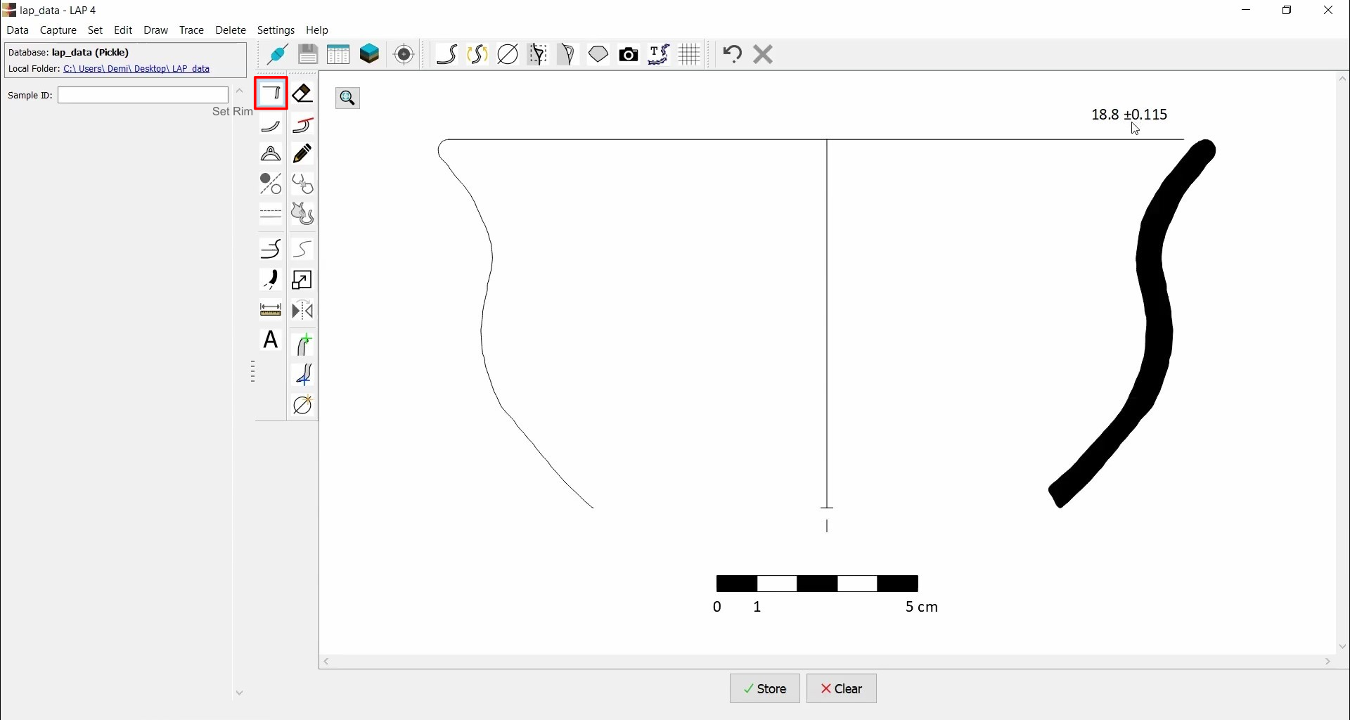 See Diameter Capture for detailed instructions.
Camera Snapshot
This step complements the drawing with a photograph of the fragment.
| Icon | Description |
|---|---|
 |
Capture Photo |
Switch to Capture Photo mode. Place a black or white paper background on the glass and position the fragment on top. Adjust white balance using Auto WB and crop the image as needed.
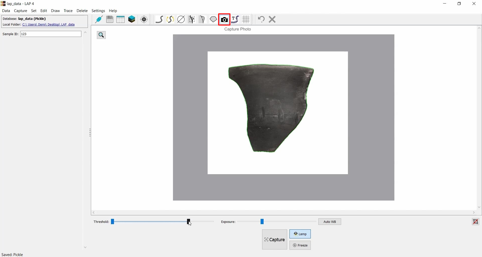
After capturing, reposition and scale the photo using the on-screen controls to align it with your drawing.
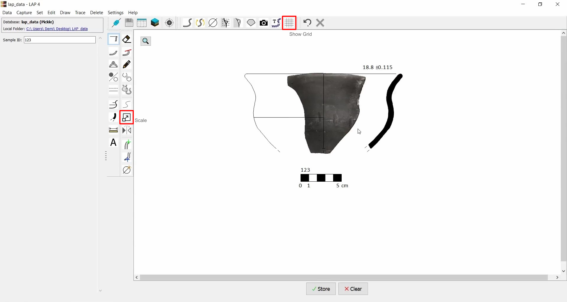
See Camera Snapshot for detailed instructions.
Save Sample Record
Enter a name in the Sample ID field in the top-left corner (e.g. 1234) — this will serve as the drawing name in the database.

Click Save to store the drawing in the database.
| Icon | Description |
|---|---|
 |
Save |
See Managing and Editing Stored Drawings for more information.